Lessons Learned
Problems and Solutions
I cannot tell a lie - I ran into a bunch of problems. The first time you build a new design, and without proven "blueprints", that is not unusual. One way to avoid that is to follow more closely than I did the details of a design that someone else has already built. The good news, though, is that all the problems had solutions...
Sputtering Return Water
When I first turned on the pump, the return water coming into the tank kept sputtering unevenly, like a garden hose will when it still has some air in it. And the pump was noisier than it should have been. There was lots of talk about whether I had primed the pump adequately. This might have accounted for the pump noise, but I did not see how that could cause the return to sputter for days. Eventually, I hooked up an air compressor to the hose bib on the tank's U-tube, closed the other valve, and capped the return pipe (Sharkbites made this simple). The pressure did not hold. I removed the glazing from the collector where the hissing sound was heard, and found an air leak on one of the silicone hose connections between panels. A clamp had cut into the hose at the very end, and the hose was not centered over the gap between the pipe ends.
Solution:
I was able to adjust the hose and re-tighten, and the leak was gone. The sputtering stopped, and the pump was quieter. Interestingly, there had been no water leak at the collector. Somehow the air leak must have imbalanced the flow in the collector such that water did not flow at all on that half. Another mysterious trait of flowing water in pipes.
Low Flow Rate
I was only getting about 2.5 gpm through the system. I was shooting for Gary Reysa's mid-range target of about 0.04 gpm per sq. ft. of collector, which would mean I needed around 8 gpm total. A lower flow rate can result in less total efficiency of heat extraction.
Solution:
I bought a new much more powerful pump (Grundfos 26-99 3-speed cast iron), which raised the flow from 2-3 gpm to almost 8 gpm on high speed. It was surprising that the flow on high speed only came to 8 gpm, but Gary re-did his pump head calculations and realized that the 3/4" CPVC pipe I used for the 45 foot run from the house to the collector has a tighter ID than he thought, and hence more resistance. Turns out there are two kinds of CPVC pipe, CTS (copper tubing sized) and ITS (iron tubing sized). I had used CTS, which has the smaller ID.
Low Heat Rise
In the first week or so after turning on the system, the 300 gallon tank rose from the mid-60's to 140 degrees. That was nice, but the temperature rise was less than it should have been. After all, this was mid-summer and I have a large collector.
Solution:
I was not getting even flow through the system, for a variety of reasons. More on that in the notes below.
Uneven Flow in Collector Panels
As part of tracking down the lower-than expected temperature rise, I removed all the glazing panels (easy since there is no caulking) and used an IR temperature gun — bought cheap on eBay — to map the temps on the whole collector. Only a total of about six of the 46 risers were getting any flow! This sparked a huge debate as to probable causes, with people recommending that I crimp the copper risers to encourage the water to flow more evenly, or insert restrictive plugs in various pipes. Luckily I did not take such drastic steps. Alan Rushforth had suggested early on that my symptoms would be accounted for if I had accidentally reversed the supply and return lines. I tried to check that, and it did not seem to be true.
Attempted Solution:
One idea was that the fact that I used a reducing elbow at the lower right and left corners (for the final riser on each side) and a reducing tee on all other risers might have led to the water flowing more easily at the outside edges — since elbows have less resistance than tees. So I cut out the elbows and added tees there, with capped stubs. No noticeable difference.
Solution:
This one is just plain embarrassing. One very humid day I was doing a long flow/temperature test with the garden hose as the supply, which meant I was putting very cold water through the system. I noticed that the
return pipes all along the bottom of the collector were covered in condensation, but the
supply pipe was only wet at the far ends. Eureka! I had in fact reversed the return and supply. On the very hot day when we dug the trench I had written on the back of the collector that the return line was on the East - but that was dead wrong. My excuse is near-sunstroke that day - but nevertheless I felt like a fool. Swapping the lines in the basement got rid of the flow-only-at-the-edges problem.
More Uneven Flow in Collector
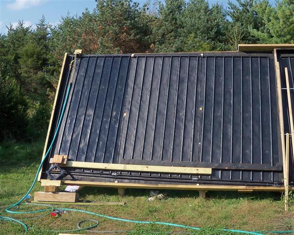
This is the toughest problem I faced. After fixing all prior problems, I found via a temperature test of the collector surfaces, with glazing off, that water was flowing evenly in the left half of the collector, but virtually not at all — or perhaps not at all — in the right half. As it happens, the highest point on the right half is more than 3/4" higher than the highest point on the left half. Alan Rushforth (he who was right about my reversed supply/return lines) suggested that the flow could have been satisfied first on the left half, because it was just that much easier for the water to get to the top over there, and it never "needed" to flow in the right half. Water takes the easiest way.
Attempted Solutions:
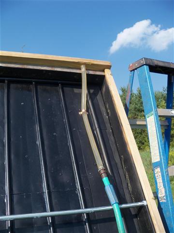
- I added a ball valve high on the return pipe on the left half of the collector, to see if restricting the return flow on that side would help. For the first test, I attached the garden hose, partially closed the valve, and saw even flow on both sides of the collector for the first time ever. Jubilation was short-lived, however, because when I used the pump instead, I got all the flow on the right half this time. I tried adjusting the valve back and forth, to varying degrees of success — finally deciding that it would be just too finicky to adjust with the valve, at least at this pressure. When the new bigger pump came, I had a similar experience: sometimes the flow would seem balanced, but then next time it would favor one side of the other. I began to doubt that any valve setting on the return pipe would produce good results consistently. If I had been able to restrict the supply line on the left with a valve that might have been more fruitful, but that would have been hard given available pipe down there. Again, people suggested using in-line restrictor plugs, but that looked like a lot of rather time-consuming trial and error experimentation.
- Since the new pump (see above) did not overcome the flow problem, I was going to remove the three right panels completely and trim them down at the bottom so that the highest point on the right is the same as on the left side (a lot of work, removing and replacing panels). However, Tom Sullivan realized that there could be a way to raise the left panels in place, without the need to remove any panels. I liked the idea and figured a way to do it. I had to remove some 2x4 dividers on the left side, remove the left half of the 2x8 header plate on top, and loosen the bottom of the 2x6 left frame piece - because as I rotated up the left panels they would push up and also push out slightly at the lower left. Then I removed all the screws that were securing the three left panels to the backing plywood. At this point the three left panels were "free" in the frame but still coupled together as one unit. I firmly screwed a long 2x4 across the three panels, near the bottom, and used a car jack bearing on timbers on the ground to push up on the left edge of that long 2x4. The panels easily rotated up. The fact that I use silicone hose to connect the panels together meant that there was no problem with strain at the center coupling.
Using a water level, I got the left and right tops of the return pipes level, then shimmed the bottom of the panels.
Sadly, I still did not get reliable even flow after making the highest point on each half of the collector at the same level. The flow was improved, but far from ideal. Some other factor was influencing where the water chose to go.
Other Possible Solutions:
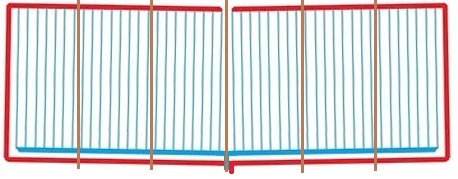
- Another idea Alan Rushforth proposed was to change the 3/4" copper return drops at each end to 1/2" pipe. The theory here is that since the supply line from the basement tank is 3/4", and we want half the water to go to the left side and half to the right side, we want to make it difficult for all the water to flow on one side or the other. If there were a 1/2" downpipe at each end of the returns, it could be that not all the water could comfortably flow through just one of those narrower pipes - encouraging it to flow on both sides. So far I have not tested this theory - see "Solution (for now") below.
- The ultimate solution (which I have not yet implemented, and may not need to) is to add an extra few inches of height to the entire collector, and change the return pipes so that instead of heading down at the outside edges, they go up at an angle from their outer top edges, and meet at a tee at the top center, and then come down in one shared pipe. The theory here is that this would ensure that the highest point for both halves of the collector is the same, and eliminate the "race" to fill one side or the other first. This is more work than the other option, which is why I save it for last - but Alan Rushforth is 99% sure this would fix the problem.
That is, instead of this:
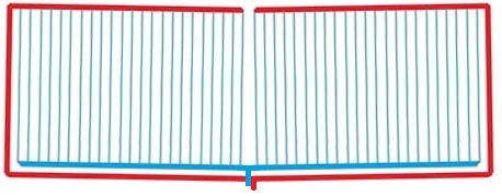
I would have this:
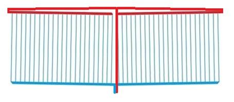
Both of the last two options would have been totally simple to accomplish at the start, but they are much harder at this stage. Any new collector of this kind of design should probably take the shared apex approach from the start, which should overcome any small differences in the heights of the two sides.
Solution (for now):
I already had a ball valve near the top of the left side's return downpipe. I added another ball valve on the right side's return downpipe. If I partially closed both, I figured that the resulting restrictions on both sides might encourage the water to flow through both. I thought this might achieve an effect somewhat like that of switching to 1/2" downpipes. Whether it is as effective as that would be I do not yet know. But for now, I seem to have even flow on both sides of the collector. At least for this season (October 2010), I decided that I am done, and I put the glazing panels back up. The system has been heating quite well.
For future panel temperature monitoring without the need to remove glazing, John Canivan provided six thermistors and a simple test board. I attached the thermistors at the same spot in each of the six panels, and ran the wires to the back of teh panel, where I keep the test board in a sealed plastic container. Using an ohm meter and the test board, I can check the temperature inside each of the six panels to determine the evenness of the flow. Here is a
video of the test setup.
The Trench
As already mentioned, I did not take into account the depth of the swale that exists about 12 feet from the house, when planning the slope and depth of the trench. A swale is a very gentle depression in the ground that is created so that rain water will run there rather than elsewhere — in this case, to keep the water away from the foundation. On that super-hot day when we dug the trench and laid the pipes into it, I discovered to some horror that the top of the insulating block around the pipes would only be inches below the ground level at the lowest part of the swale. But I could not risk it raining on an open trench, and the sun was going down, so I decided to live with it. Well, it did rain — a lot — and enough water worked into the loose fill in the trench that it literally floated the insulation block up above ground level. (No picture, too horrifying.) This is also when the basement flooded, though that was not due to the trench problems, just to the fact that I had not sealed the opening yet.
Solution:
Excavate the pipes and their insulation block. Cut that off with a repirocating saw 10 feet from the collector, to preserve the connections to the collector. Dig the trench at least a foot deeper. Drill a new set of holes lower down in the foundation. Repair the strains in the insulation block. Splice the pipes and insulation to the remaining piece. Fill it, seal the basement hole - and we have been good so far even with heavy rains.
The Boiler - Blowing a Fuse
After I hooked up the relays and tried out the radiant floor system with the solar loop and the boiler loop, I blew a 5A fuse in the boiler's internal control panel twice. Some head-scratching followed, but I finally had the idea that what might have been blowing the fuse was the extra strain that gets put on the pumps (over and above what the boiler circuit "expects") when the system cuts over from the solar loop to the boiler. The 3-way valve I use to direct water through the tank heat exchanger or through the boiler takes a number of seconds to fully open or close. So when we cut over from solar to boiler, the pumps - now under boiler-supplied power - have to push the water through 100 ft of 1/2" copper coil in the tank for a little while. Normally, the boiler has 1" copper to deal with, and then manifolds that share the flow between many parallel pex runs. So the extra 100 ft of 1/2" constriction could produce significantly more power draw on the pumps for those few seconds.
Solution:
As described on the Heating the House page, I brought in external power to drive the pumps, so that the boiler's 120v output is now only used to throw a relay to connect the pumps to the external power. The fuse is fine.
Pipe Expansion
I had known that CPVC expands and contracts a lot with heat and cold. I had hoped, based on others' experience, that the 50 foot run of CPVC from the house to the panels would handle expansion by slightly bending along its length. The pipes can go from sub-freezing to 140 degrees when the pump turns on in winter. In my case, one of the pipes seems to handle the expansion well. The other one, however, seems unwilling to absorb the change by bending, and instead the change of length causes it to force the end inside the foundation to push in an out as the temperature swings. The pipes are surrounded in the foundation hole by expanding foam, and that provides little resistance to this movement so the pipe slides in and out about 1.5 inches. This loosened up the seal a bit, and I got some water dripping in after a very heavy rain.
Solution:
I tried to seal the opening some more, and also graded the earth better above the foundation penetration, and Im keeping my fingers crossed. In retrospect I might have chosen to use hydraulic cement to seal the opening. The drawback is its permanence, but it should make a much stronger seal.
Things I Would Do Differently
Make the copper arrays the same slope and height
I did not think that the
exact slope of the two sets of three copper arrays mattered all that much, as long as they both had a good strong slope toward the center for drainage. As you can see in the "problem" discussed
above, the fact that I ended up with the right array more than 3/4" higher at the end than the left array may have had serious side effects. Uniformity would have been easy to achieve had I known.
Use a "shared apex return" design
See the
flow problem discussion above, and the final proposed solution. This approach should overcome slight differences in array heights on a design like mine, and would be completely simple to implement in the first place.
Use larger pipe
I would use a larger-diameter pipe for the 45 ft run to and from the house, to decrease resistance and allow the use of a smaller pump that uses less power. I would probably stick with CPVC, but would go to 1" pipe. It might be easiest to connect to other piping if I used regular CTS (copper tubing sized) CPVC, but if I could find suitable connectors then IPS CPVC would provide even more ID and less resistance. This would require changes in the foam-based channel that insulates the underground pipes.
Make the collector's plywood panels and glazing panels uniform in size
The separate 4x8 panels in the collector were not really 4x8. One reason is that the overall collector is 8' tall, and the 2x lumber that frames the collector eats into that by 3".So that makes the panels less than 93" tall, which is fine. Similarly, the width will be less than 48" each, also fine. But the way I laid things out, the widths of the panels varied. This should be avoided, because uniformity is very good thing. I was trying to avoid having any of the vertical 2x4s that divide the collector fall on top of or too close to any of the copper piping, given the significant slope I built into the arrays.
This diagram shows more or less where the 2x4 dividers had to fall:
It's a little hard to convey the issue here, but what I would do if I did this again would be to make the space between each of the six copper arrays a little bigger. That would provide more leeway for where the 2x4 dividers could go, to make their spacing uniform. I made the spacing between copper risers the same all across a set of three arrays. It would be better to make the gap between each panel larger — that is, the gap between the last riser of one panel and the first riser of the next. This also has the extra advantage of allowing a larger gap between the copper stubs on each panel. When connecting panels with silicone hose, as I did, this makes it simpler to deal with any slight discrepancies in the way these stubs line up (as the hose is bendable). And this allows for longer copper stubs, which can make it easier to clamp the hose effectively.
If the 2x4 dividers are evenly spaced, and the space between the last dividers and the 2x6 edge boards is also the same, then the width of all the glazing panels will be the same as well, also a convenience. Note that the glazing panels fit beneath the 2x8 header on the collector (on an extra 2x4 attached there as glazing support), but they also extend down partly over the bottom 2x6 of the collector, so the glazing height is a bit more than the height of the plywood array panels.
Note that it is also good to take into account where the support 2x4's lie at the back of the collector frame when planning where the internal 2x4 dividers will go. It's easiest and most solid to screw into the internal dividers from the back, but obviously that is not easy if the 2x4 supports are in the way. Designing everything in detail on paper before you build is the way to go.
Later Note: "Best practices" for building arrays like these continue to evolve, as can be seen on builditsolar.com. I might consider dispensing with the plywood panels to which the copper arrays were attached. The copper arrays could be sandwiched with aluminum, held tightly together by small screws, and each array set into the frame right on top of the insulation, or perhaps with a thinner piece of plywood set in between. I would also consider making the overall array frame larger so that I could use full size 4x8 twinwall panels, with no cutting involved. The frame is easy to build, of course, using 4x8 plywood sheets, but it could be made a bit larger than the 6 plywood sheets easily enough. The key is in sizing eveything, and placing the 2x4 verticals, so that the twinwall panels will line up where they need to be, given the batten system being used.
Make the copper arrays line up exactly
On adjoining arrays, make the copper stubs that connect the arrays together line up perfectly. This can be done most easily by making a measuring jig to be sure that the height of the copper arrays is always the same when you soldere them up, especially at their edges. Even though I used jig-cut copper risers which were quite uniform in length, the soldered panels ended up different by fractions of an inch.
Make the fin grooves deeper
Use a 3/4" rod and jig for forming the fins for 1/2" pipe, rather than the 5/8" I used. This provides more aluminum to bend farther around the copper pipe with a clamping jig. (Gary experimented with a 5/8" rod and a 3/4" groove and liked the results.) Or, you might want to get some pre-formed fins from
Tom Sullivan, who has a great system for that.
Wrap the insulated supply/return pipes
When laying the insulated "sandwich" of supply/return pipes from the house to the collector, I had the thought that water might leak into the sandwich. But I did not pursue the thought. Now I realize that, since the pipe sandwich is way above the frost line, water inside the insulation can freeze and expand and potentially break open the insulation "box". It would have been smart to wrap the insulation with a strong layer of plastic sheeting.
Use less silicone caulk with the fins.
When I had to remove a couple of fins when making some plumbing changes (mentioned above in the Problems section), I noticed that there was more caulk between the pipes and the fins than seemed necessary. I would use caulk very lightly in contact with the copper, and do my best to make a tight fit with a clamping jig.
Insulate more under the tank
Between the tank water and the concrete floor in my basement shop, I have 2" of polyisocyanurate foam, 3/4" of plywood, and another 1" of polystyrene foam board. I thought that would be enough. But tonight I was in bare feet in the shop and happened to stand right next to the tank. The concrete right by the tank was considerably warmer than the rest of the floor. The tank has been above 150 degrees most of the time, sometimes at 160 on a sunny day (mid-October), and apparently that much heat will easily push its way through the amount of insulation I used. I would put more foam down there "next time". I have 4" of foam on sides and top already.
Changes
Switching to aluminum channel rather than wood batten strips
See the
Introduction page for a discussion of how and why I switched to aluminum channel, and why I'm not sure it was the best idea.
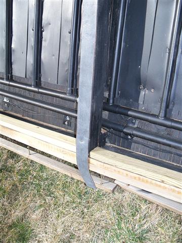
Aluminum corrodes on pressire treated wood, so I added a strip of EPDM rubber (left over from tank):
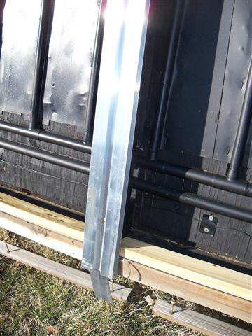
Aluminum H channel:
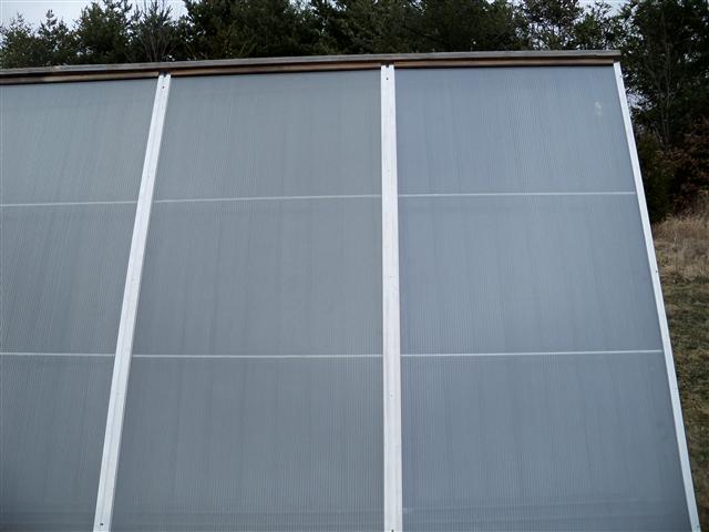
Finished look:
 Next page (Contact and Thanks) >>